





How to use a wire rope breaking strength chart without overrating WLL
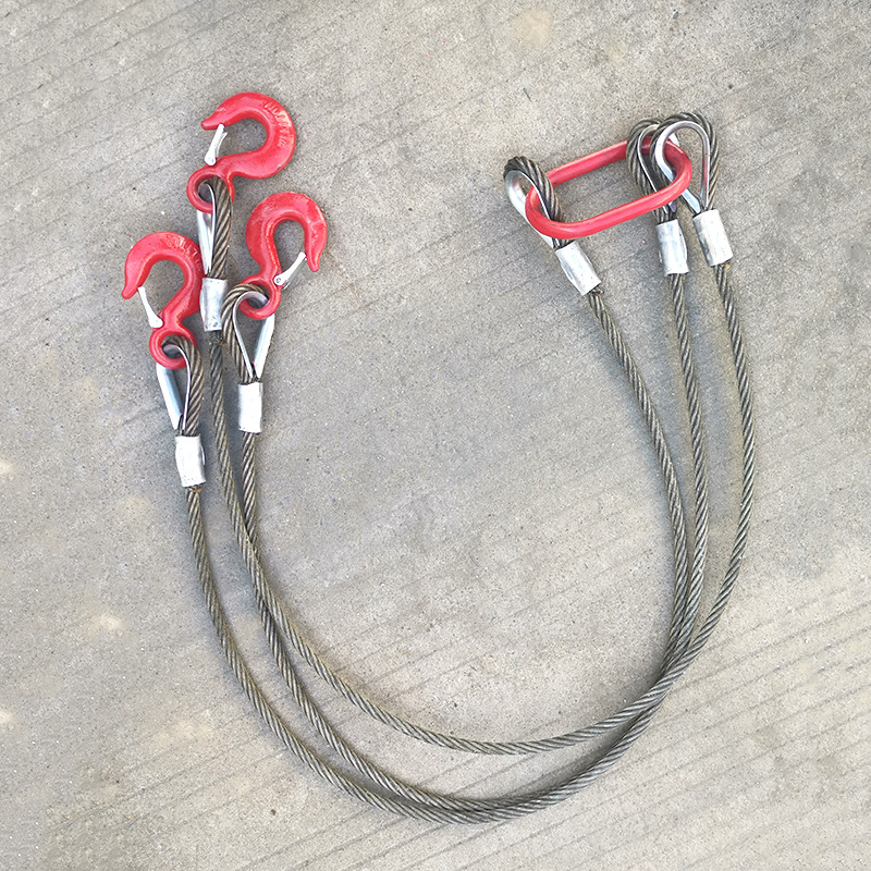
A wire rope breaking strength chart is a selection reference, not a permission to lift at the number shown. The figure in the chart normally represents minimum breaking force or nominal breaking strength under controlled test conditions. It does not automatically account for terminations, sling geometry, wear, shock loading, side loading, or the rules that govern a particular lifting operation. Treating the chart value as the working load limit (WLL) can create a serious overrating error before the rope ever reaches the job site.
This issue often appears during equipment review or replacement. A rope diameter and construction are matched to a chart, the breaking-strength figure looks comfortably high, and the selected assembly is labeled or used at a much higher capacity than its termination or configuration permits. The correct approach is to start with the chart, then reduce the result through the applicable design factor, termination efficiency, and service conditions. The final WLL must be based on the complete assembly, not on the bare rope alone.
Read the heading before reading the numbers
First identify exactly what the chart is reporting. Manufacturers may use terms such as minimum breaking force (MBF), minimum breaking load (MBL), nominal strength, or calculated breaking strength. These are related concepts, but the chart heading, unit system, rope grade, and stated basis matter. A value for a 6×19 galvanized rope is not interchangeable with a value for a 6×36 construction of the same nominal diameter, even when both are described as general-purpose steel wire rope.
Before using any row in a wire rope breaking strength chart, confirm these identifiers:
- Nominal rope diameter, including whether the dimension is metric or imperial.
- Construction, such as strand count, wire arrangement, core type, and rotation-resistant classification where relevant.
- Wire grade or tensile class used to calculate the published strength.
- Finish and material, including bright, galvanized, stainless steel, or plastic-coated rope.
- Whether the listed value applies to a new, unaltered rope sample.
- The standard, manufacturer documentation, or product specification that governs the intended application.
A chart is only valid for the rope it describes. Diameter alone is not a sufficient basis for capacity assignment. A safety manager reviewing incoming materials should therefore compare the rope marking, certificate, packing label, and purchase specification with the actual chart reference. If the construction or grade cannot be confirmed, the published breaking figure should not be used to establish a lifting WLL.
Convert breaking strength into an initial WLL
The basic relationship is straightforward:
Initial WLL = minimum breaking force ÷ required design factor
The required design factor is not a universal number. It depends on the intended use, applicable rules, equipment design, and whether the rope is part of a lifting sling, winch system, elevator installation, crane hoist, or another engineered arrangement. A rope used for a non-lifting restraint can be evaluated differently from a rope installed in a personnel-related or overhead lifting application. Do not select a convenient divisor simply because it produces the capacity needed for the lift.
For example, if a chart reports a minimum breaking force of 100 kN and the applicable design factor is 5:1, the starting WLL is 20 kN. That is only a starting point for a bare rope in the stated condition. The assembly may need a lower rating once its end fittings and actual use are considered.
It is also important not to confuse design factor with a test ratio. Some product information may state that an item is proof tested or that its breaking strength is several times a stated load. That statement does not establish the WLL of a different product, a different grade, or a complete rigging arrangement. WLL must be traceable to the item’s own specification and intended service.
The termination can control the rating
Wire rope rarely works as an unmodified straight length. It is commonly terminated with swaged sleeves, wedge sockets, poured sockets, wire rope clips, thimbles, eyes, or mechanical fittings. Each method has its own efficiency, installation requirements, inspection criteria, and limitations. A termination that does not develop the full strength of the rope reduces the allowable assembly capacity accordingly.
Consider a rope whose initial calculated WLL is 20 kN. If the approved termination efficiency is 80%, the assembly cannot be rated at 20 kN merely because the rope itself had sufficient minimum breaking force. Its capacity must be evaluated using the approved termination data and any required additional reduction. Improperly installed clips, incorrect clip quantity, reversed saddle orientation, damaged thimbles, or an eye that is too small for the connecting hardware can reduce performance further.
For quality control, the practical rule is simple: a rope chart does not replace assembly documentation. The rope, socket, sleeve, eye, hook, and identification tag must agree with the rated capacity being claimed. When a termination has been field-made and its installation cannot be verified, it should not be assumed to carry the same WLL as a factory-fabricated sling.
Account for the way the rope will be loaded
Even a correctly rated single-leg rope assembly can be overrated by the rigging arrangement. The chart value applies to axial tension. Real lifts introduce angles, bends, contact pressure, motion, and sometimes uneven loading between legs.
Wire rope condition is another separate limitation. Broken wires, corrosion, reduction in diameter, crushing, birdcaging, heat exposure, and damaged lubrication all affect continued suitability. A breaking strength chart describes new rope; it does not provide a formula for upgrading the WLL of rope that has already been in service. Inspection findings should be assessed against the applicable discard criteria and the rope manufacturer’s instructions.
A practical review sequence for incoming rope and fabricated slings
When a new rope or sling is proposed for a task, begin by defining the maximum load and the load path. Include the weight of lifting accessories, not only the object being moved. Then identify whether the operation is a straight vertical lift, a bridle lift, a choke arrangement, a winch pull, or a fixed support application.
- Match the rope’s actual diameter, construction, grade, and finish to the correct manufacturer chart.
- Record the stated minimum breaking force and the chart source used.
- Apply the design factor required for the intended equipment or lifting arrangement.
- Apply the rating limitation of the selected termination, socket, eye, or fitting.
- Apply approved reductions for hitch type, sling angle, bending conditions, or system configuration.
- Compare the resulting WLL with the maximum expected service load, including foreseeable dynamic effects.
- Confirm that the finished assembly is marked or documented with a traceable rated capacity.
The order matters because the lowest approved component or condition governs. A high-strength rope cannot compensate for an undersized hook, an unverified pressed eye, a poorly selected shackle, or a sharp contact point. Likewise, a component with a high stated breaking force should not be assumed suitable for overhead lifting unless its grade, marking, proof-test requirements, and intended use support that assignment.
Do not transfer rope-chart logic to ordinary chain
Chain is often used alongside wire rope for securing, connecting, hauling, or lifting-related tasks, but chain ratings must be taken from the chain’s own grade and product documentation. Link length, material, weld quality, heat treatment, and intended duty all influence suitability. An electrically galvanized ordinary chain may be appropriate for connections, light bundling, workstation fixing, storage binding, or selected transport and dragging duties, yet it should not inherit a wire rope sling’s WLL simply because its diameter appears similar.
For applications where the intended chain product and duty are clearly defined, review the specifications for the Welded Steel Electric Galvanized Ordinary Short Medium Long Link Chain against the actual load direction, connection method, and required rating. Short, medium, and long link patterns differ in flexibility and geometry. The stated tensile or breaking information must still be separated from an approved working-load rating for the specific use.
When the chart should not be used alone
A chart is insufficient by itself when the lift involves personnel, critical loads, severe corrosion, elevated temperature, unusual reeving, rotation-sensitive loads, repeated high-cycle service, or a nonstandard fabricated assembly. It is also insufficient when the rope has no reliable identification or when a replacement rope differs from the original equipment specification. In these situations, the equipment documentation and the applicable technical requirements should determine the selection.
The safest habit is to treat the chart as the first verification document: it establishes the strength of a defined new rope. The WLL comes later, after the required design factor and every limiting feature of the finished, inspected system have been applied.
Navigation
Send Us A Message



Shandong Faster Technology Co., Ltd. is a professional manufacturer of steel wire ropes.
Get in Touch
*We respect your confidentiality and all information are protected.