





What determines the minimum bend radius for steel cable strand?
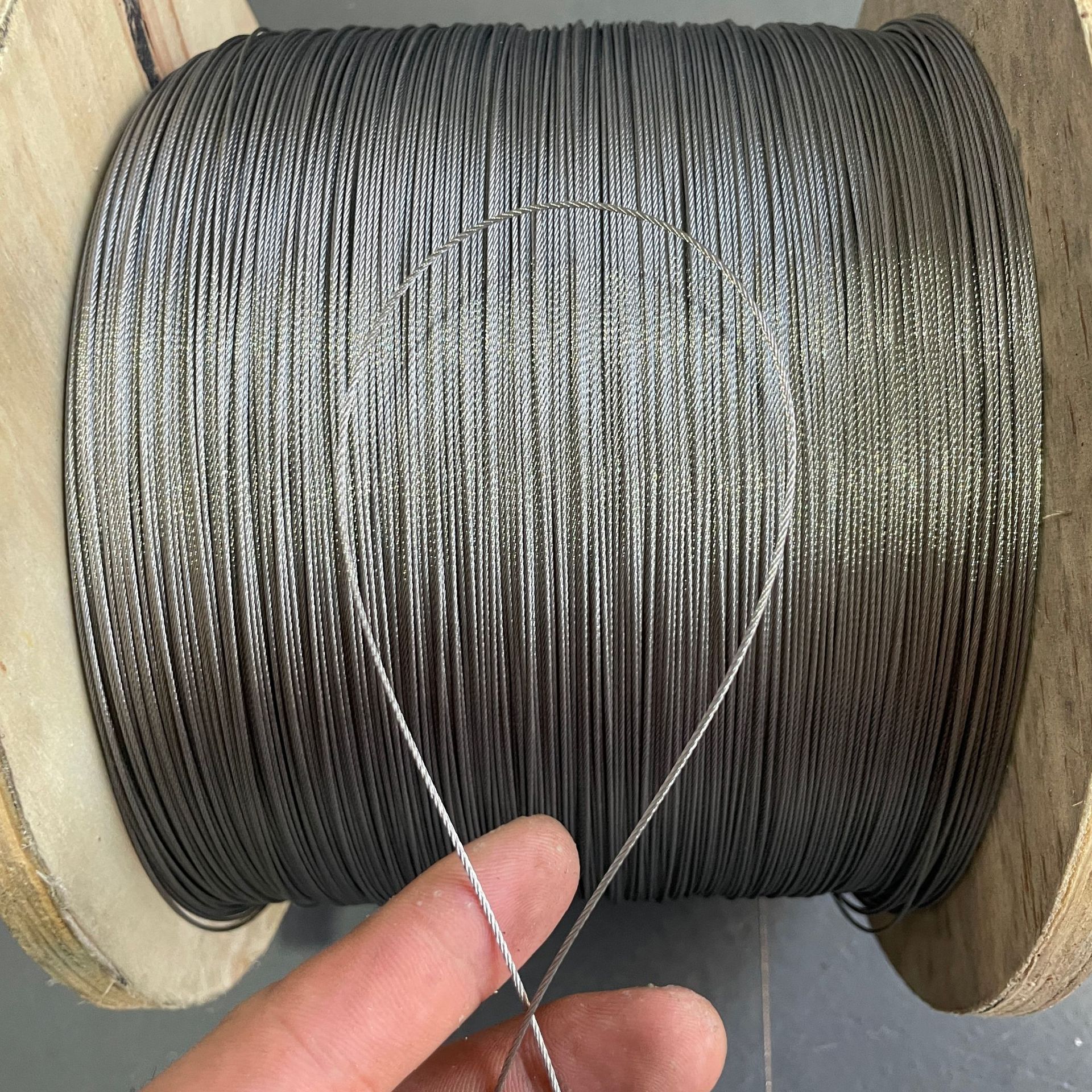
When a steel cable strand is forced around a sheave, drum, guide pulley, or termination point that is too small, damage often begins before it is visible. The strand may flatten slightly, individual wires can develop high local stress, and repeated travel over the bend accelerates fatigue. In lifting, traction, elevator, marine, and automated equipment, this can lead to broken wires, loss of dimensional stability, poor tracking, or an unexpectedly short replacement interval.
The minimum bend radius for a steel cable strand is determined primarily by its construction and diameter, then adjusted for wire grade, material condition, loading, bending frequency, and the geometry of the device it runs over. There is no single radius that applies safely to every steel cable strand. The practical decision is usually expressed as a D/d ratio: the diameter of the sheave, drum, or curved support surface (D) divided by the nominal strand diameter (d). A larger D/d ratio reduces bending stress and generally improves fatigue life.
Construction is the starting point
Not all steel cable products bend in the same way. A flexible multi-strand wire rope contains several strands around a core and is designed to articulate repeatedly. A single-strand construction, by contrast, behaves more like a compact structural cable. Its wires are tightly laid together, giving high rigidity and low torsion, but also making it less tolerant of small-radius bending.
A 1x19 strand is a clear example. Nineteen wires are twisted directly into one compact strand. This arrangement is useful where a straight, stable line is needed for tensioning, supporting, bracing, speed-limiter applications, or controlled traction. However, the same compact construction that provides rigidity means it should not be treated as a highly flexible running rope. Where the line must pass repeatedly over small pulleys, a more flexible rope construction may be more appropriate.
For this reason, the question is not simply “What is the diameter of the strand?” It is also “Is this a static bend, an occasional bend during installation, or a continuously reversing bend in service?” A strand that remains fixed around a properly formed termination can often tolerate conditions that would be unsuitable for a line cycling over a sheave thousands of times.
How bending creates stress inside the strand
When a straight strand is bent, the wires on the outside of the curve are stretched while those closer to the inside are compressed. The smaller the bend radius, the greater this difference becomes. In a tightly compacted construction, wire movement is limited, so bending strain is transferred more directly into the wires themselves.
The risk is not limited to immediate overload. Repeated bending produces alternating stress. A strand may remain below its nominal breaking load and still fail early because each pass over a small sheave repeatedly strains the wires at the same contact zone. Surface wear, imperfect grooves, corrosion, and side loading make this process faster.
Safety managers should distinguish between minimum strength and service life. A bend radius that does not visibly damage a new strand during assembly may still be too tight for long-term cyclic use. Quality control should therefore evaluate both the installation condition and the expected number of bending cycles.
Factors that change the required bend radius
Nominal diameter and wire diameter
A larger overall strand diameter normally requires a larger bend radius. Yet two products with the same nominal diameter may respond differently because their individual wire diameters differ. A construction containing fewer, larger wires is generally stiffer and more sensitive to bending than one made with more, finer wires. This is why construction must always accompany diameter on drawings, purchase specifications, and inspection records.
Material grade and surface condition
Higher tensile wire grades can provide greater minimum breaking force, but increased strength does not automatically mean better tolerance of tight bending. High-strength wire can be more sensitive to surface damage and fatigue concentration. Stainless steel, galvanized steel, and plastic-coated products also need separate consideration. Coating may improve corrosion protection or external contact behavior, but it does not remove the internal bending stresses imposed by an undersized sheave.
Corrosion is particularly important where a strand operates outdoors, near salt water, or around chemicals. Pitting creates stress raisers in individual wires. A radius that may be acceptable for clean, dry, lightly cycled service can become a poor choice where corrosion and bending fatigue act together.
Static, moving, and reversing service
A cable used as a fixed architectural support or a tension member may only be bent once during installation. The main concern is avoiding kinks, crushing, and an excessively sharp termination bend. A traction line that moves over a pulley requires more margin. Reversing service is more demanding still because the strand bends alternately in opposite directions.
- Static service: assess the formed bend, termination geometry, tension level, and risk of vibration.
- Occasional movement: account for guide alignment, possible abrasion, and whether the line is bent at the same point repeatedly.
- Continuous running: use the equipment manufacturer’s D/d requirement and select a construction intended for bending fatigue duty.
- Reversing or high-cycle motion: give priority to fatigue performance, groove condition, fleet angle, lubrication requirements, and inspection frequency.
The sheave or drum can be the real limiting factor
Even when the calculated sheave diameter appears adequate, a poorly designed groove can shorten strand life. The groove should support the strand without pinching it, allow it to seat consistently, and avoid sharp edges. A groove that is too narrow can flatten the strand or damage its surface. One that is too wide can allow unstable contact, vibration, and localized wear.
Drum winding introduces additional concerns. Multi-layer winding can create cross-over pressure and local reverse bends. A stiff single strand may not pack or transition smoothly in a drum system designed for a more flexible rope. Side loading caused by poor alignment, excessive fleet angle, or mispositioned guides also creates contact stresses that are not captured by the D/d ratio alone.
During inspection, look for a polished wear band concentrated on one side, flattened areas, changes in strand diameter, birdcaging in rope constructions, cracked coating, or recurrent wire breaks near the same sheave. These signs point to a geometry or alignment issue, not merely normal wear.
Use standards correctly without treating them as a universal radius table
Standards such as EN 12385-4 and applicable national specifications provide important requirements for wire rope products, including dimensional and strength-related information. However, the appropriate minimum sheave or drum diameter depends on the product category and the machinery application. The governing equipment standard, the rope or strand manufacturer’s data, and the design duty must be read together.
A minimum breaking load is not a bend-radius recommendation. For example, a product may have verified breaking-force values at a stated wire grade, but its suitability for a small traction pulley still depends on construction and operating conditions. Do not substitute a strength table for a fatigue or sheave-design assessment.
A practical review before approving a steel cable strand
Start with the exact product designation: nominal diameter, construction, material, tensile grade, coating, and intended duty. Then record the smallest effective diameter the strand will encounter, including pulleys, drum cores, guide rollers, termination pins, and any temporary installation path. Measure the working surface rather than relying on an outside flange dimension.
- Identify whether the strand is stationary, intermittently moving, continuously running, or repeatedly reversing.
- Confirm the smallest D/d ratio in the entire route, not only at the main sheave.
- Check groove profile, edge condition, alignment, fleet angle, and whether the strand can rub against adjacent hardware.
- Compare the construction with the manufacturer’s intended application; do not assume a rigid strand is suitable for high-cycle pulley duty.
- Set inspection points around bends, terminations, and sheaves where fatigue and abrasion are most likely to appear first.
For compact corrosion-resistant traction or support applications, 1x19 Stainless Steel Wire Rope 0.4-5.0mm use For Traction Drive is available in 201, 304, 316, and 316L stainless steel options. Its 1x19 construction offers high rigidity, low torsion, and axial tension capability in diameters from 0.4 mm to 5.0 mm. Those characteristics can be useful in constrained installations, but the design should preserve an appropriate bending radius rather than relying on compact size alone.
When the bend radius should be changed instead of the strand
Sometimes the correct remedy is a larger sheave, a redesigned guide, or a smoother termination path. This is usually preferable when the existing strand construction is needed for stiffness, low stretch, positioning accuracy, or corrosion resistance. Enlarging the bending component reduces stress without changing the functional behavior of the line.
Changing to a more flexible construction may be the better answer when repeated bending is unavoidable and equipment dimensions cannot be increased. That decision should account for changes in rotational behavior, elongation, abrasion resistance, termination method, and minimum breaking force. A more flexible product is not automatically interchangeable with a rigid steel cable strand in a traction or positioning system.
The safest specification is therefore based on the complete system: strand construction, smallest bend, motion pattern, load, environment, and inspection access. When these conditions are documented before installation, premature wire breakage is far more likely to be prevented at the design stage rather than discovered after service damage has begun.
Navigation
Send Us A Message



Shandong Faster Technology Co., Ltd. is a professional manufacturer of steel wire ropes.
Get in Touch
*We respect your confidentiality and all information are protected.