





Steel Wire Rope Basics: Why Breaking Strength Is Not a Working Load Limit
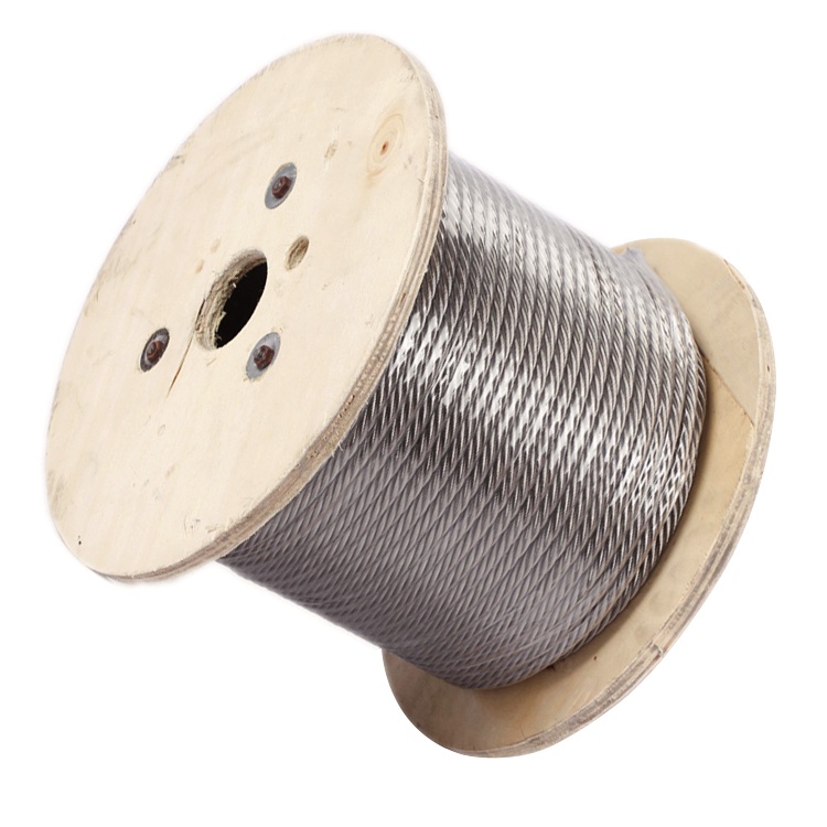
A steel wire rope specification lists a breaking force of 100 kN. Does that mean it can safely lift a load approaching 100 kN? No—and the difference is not simply a little extra caution. Breaking strength describes resistance to failure under specified test conditions. A working load limit describes the maximum load permitted for a defined product, configuration, and service conditions.
For anyone comparing ropes for lifting, marine work, construction, or mining, that distinction matters. A rope does not work alone: terminations, hooks, sling angles, bending, wear, and load movement all affect the forces it must withstand. Understanding the numbers helps you ask better questions before a purchase—and avoid treating a laboratory value as permission to lift.
What steel wire rope breaking strength actually tells you
Steel wire rope consists of individual wires arranged into strands, which are then laid around a core. Its strength depends on more than diameter. Wire tensile grade, construction, metallic cross-sectional area, core type, and manufacturing quality all influence performance.
Supplier documents may use terms such as minimum breaking force, minimum breaking load, or actual measured breaking force. These are related, but they are not interchangeable:
- Minimum breaking force: the specified minimum force that a new rope must meet under the applicable test requirements.
- Actual breaking force: the result obtained when a particular test specimen is pulled to failure.
- Working load limit (WLL): the maximum load assigned to a product for specified conditions of use.
A test result above the specified minimum does not authorize a higher working load. Nor does the strength of new rope describe the remaining capacity of rope that has suffered corrosion, crushing, or fatigue.
Also watch the units. Breaking force is commonly expressed in kN, while WLL may be marked in kilograms or tonnes of supported mass. Wire tensile strength, expressed in N/mm², is a material stress value—not the lifting capacity of the finished rope.
Why a design factor separates failure from everyday work
A design factor establishes a relationship between a defined breaking strength and an allowable working load. In a simplified calculation:
Allowable working force = applicable minimum breaking force ÷ required design factor
Suppose a new rope has a minimum breaking force of 100 kN. If the governing requirements specify a design factor of 5 for the particular application, the simplified result is 20 kN. That is approximately the gravitational force associated with a mass of 2.04 tonnes—not a 10-tonne lifting capacity.
This is an illustration, not a rating recommendation. The required design factor varies with the application, equipment, standard, and jurisdiction. A crane hoist rope, an elevator suspension rope, and a fabricated lifting sling cannot automatically be rated using the same rule.
For an assembly, the calculation must also account for its connections and configuration. A termination that develops less than the rope’s full strength changes the applicable strength basis. Hardware can impose a lower limit still. The finished sling’s documented rating is therefore more useful than a calculation made from a bare-rope catalog.
A design factor is not spare capacity available for occasional overloads. It forms part of the engineering basis for safe service; it does not make shock loading or damaged equipment acceptable.
The load on a rope is not always the weight being lifted
A suspended load can look steady while its individual sling legs carry surprisingly high tension. Geometry is often the reason.
Sling angles change leg tension
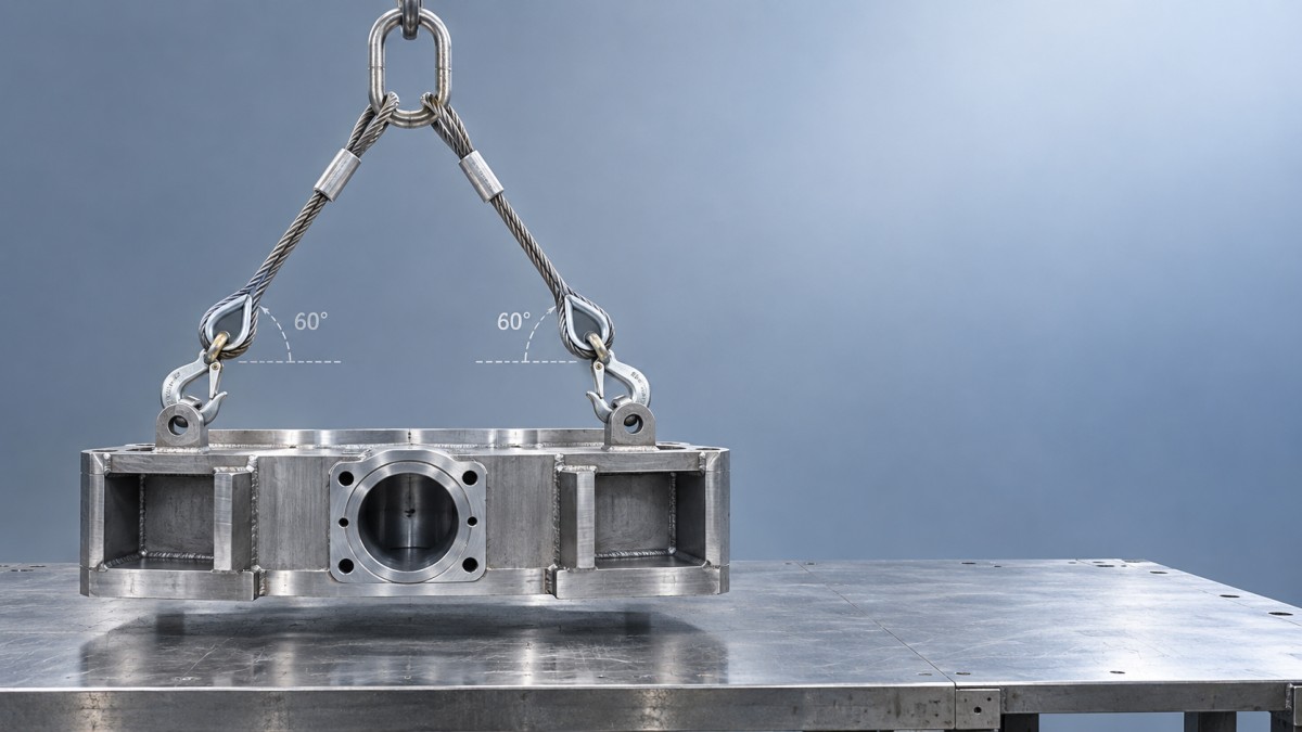
For an ideal, symmetric two-leg lift with equal load sharing, leg tension can be illustrated as:
Leg tension = load weight ÷ (2 × sin θ), where θ is the angle of each leg measured from the horizontal.
At 60° from horizontal, each leg carries approximately 58% of the load weight. At 30°, each carries an amount equal to the entire load weight. As the legs become flatter, their tension increases sharply.
This equation explains the principle, but it is not a substitute for the manufacturer’s sling rating chart. Unequal leg lengths, an offset center of gravity, or unsuitable attachment points can invalidate the equal-sharing assumption.
Four legs do not guarantee four-way load sharing
A four-leg bridle offers multiple attachment points and can improve stability, but it should not be assumed that each leg carries exactly one-quarter of the load. Small differences in length, load stiffness, and attachment geometry may leave some legs carrying much more than others. Applicable rating methods may therefore use fewer effective load-bearing legs than the assembly physically contains.
A practical example is the 4 Leg Wire Rope Sling Carbon Steel With Latched Eye Sling Hook for Heavy Lifting offered by Shandong Faster Technology Co., Ltd. Its four single-part rope legs connect through an oblong master link, with thimble-protected eyes formed by mechanical splicing and latched hooks at the leg ends. These components create a usable lifting assembly, but its allowable load must still come from the documented assembly rating for the intended angles and conditions—not from adding together four rope breaking strengths.
The hook latches help retain the connection; they are not load-bearing elements and do not make side loading or tip loading acceptable.
Movement introduces additional forces
Sudden acceleration, taking up slack abruptly, or attempting to free a stuck load can produce forces well above the load’s static weight. Vessel motion and swinging loads introduce further uncertainty. Where dynamic loading is expected, the equipment and operating method need specific assessment rather than an informal reduction of the catalog capacity.
Where the complete assembly can lose strength
Even correctly selected rope can be compromised by how it is connected or routed. These details deserve attention before diameter alone drives the buying decision:
- Terminations: ferrule-secured eyes, splices, sockets, and clips have different installation requirements and efficiencies. Use the approved method and documented capacity.
- Bending: small sheaves, drums, or pins can impose severe bending stresses. The relationship between bending diameter and rope diameter affects performance and fatigue life.
- Hitch arrangement: straight, basket, and choker configurations have different ratings and limitations.
- Contact with the load: sharp edges and small contact radii can damage the rope. Suitable protection and an approved arrangement may be necessary.
- Condition: broken wires, corrosion, kinks, crushing, and heat exposure can require removal from service under the applicable inspection criteria.
Core selection matters too. An independent wire rope core generally provides greater resistance to crushing and less stretch than a comparable fiber-core design. However, neither core type establishes WLL on its own. Likewise, galvanizing or a plastic coating does not create an extra load allowance; coatings can also make underlying deterioration harder to see.
What to ask for when comparing steel wire rope
The useful question is not simply “How strong is this rope?” It is “What is this product rated to do in my actual arrangement?” Ask the supplier for:
- The rope diameter, construction, core, material, and specified minimum breaking force.
- The applicable standard and design-factor basis.
- The finished assembly WLL, including permitted sling angles and hitch configurations.
- Termination details and compatible, rated hooks and master links.
- Traceable identification, supporting documentation, and inspection instructions.
Shandong Faster manufactures steel wire rope and customized slings, including galvanized, stainless steel, and plastic-coated rope options in the 1–20 mm diameter range. For a customized assembly, providing the load weight, center of gravity, attachment spacing, required leg lengths, and operating environment is more useful than requesting a particular breaking strength alone.
The essential distinction is simple: breaking strength describes a failure threshold; WLL defines a permitted working load under stated conditions. Choose by the complete assembly’s documented rating, verify that the lifting arrangement matches that rating, and keep condition and inspection in the decision. The largest number on a specification sheet is rarely the number that should guide the lift.
Navigation
Send Us A Message



Shandong Faster Technology Co., Ltd. is a professional manufacturer of steel wire ropes.
Get in Touch
*We respect your confidentiality and all information are protected.